
FairCurveModeler
Описание
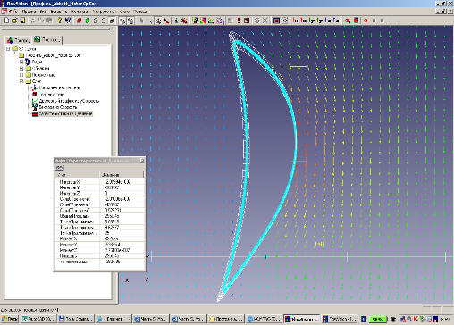
FaiCurveModeler app (ZWCAD, BricsCAD, AutoCAD) for geometric modeling of products with functional curves and surfaces. The application is implemented based on the innovative FaiCurveModeler section of the C3D geometric kernel. The application implements all the functionality of the C3D©FairCurveModeler section. And in this sense, he is a full-fledged representative of it. The FaiCurveModeler application is designed for geometric modeling of products with functional curves and surfaces. The geometric parameters of functional surfaces are decisive for the functional characteristics of the designed object as a whole. The use of C3D©FairCurveModeler methods allows you to obtain curves of the highest quality (class F): high order of smoothness (up to 9th order), with a minimum number of curvature extrema, with a smooth change in curvature with limited variation and with a limitation on the rate of change, with a smooth torsion of spatial curve. First of all, applications of FairCurveModeler is offered for users of specialized CAD-systems which program developers declare their ability to model curves and surfaces of high quality. These users really need the features of modeling curves and surfaces of high quality. And such functionality, but provides a better quality of curves and surfaces, they will find in the application FairCurveModeler (see curves comparison FairCurveModeler vs NX and 'Alias Design Studio') and (see comparison of surfaces FairCurveModeler vs NX, Rhinoceros 3D and Alias Design Studio) The second group of users who need web-application FairCurveModeler, - are users who manage in the design of the standard mechanical engineering CAD-systems, but who wish to improve consumer properties of a designed product with geometric shapes of high quality in terms of functionality and aesthetics (see the examples of analyzis and of improving primitive _Helix in ZWCAD). Support/14b_Improve_Helix_ZWCAD_Bz.mp4 The third group - users of graphics packages (for example, Corel Draw) and animation programs (for example, 3D MAX Studio) - designers, artists, web-designers, gamers, animators, who need to draw a just beautiful curve, beautiful surfaces using friendly and intuitive, precise types of geometric descriptors (see the examples of modeling and editing curves in the application) The geometry of various products is formed by functional curves and surfaces: 1) the profile of an airplane wing / the profile of a turbine blade creates lift. When modeling an airfoil curve, it is necessary to maximize lift while minimizing drag. The proposed modeling techniques based on the Abbott method, but using class F curves, can significantly improve the aerodynamic characteristics of standard TsAGI, NACA profiles and profiles of turbine and compressor blades. Comparative testing of the original airfoils and the improved airfoils in the FlowVision system shows a significant increase in aerodynamic efficiency of the improved airfoils.
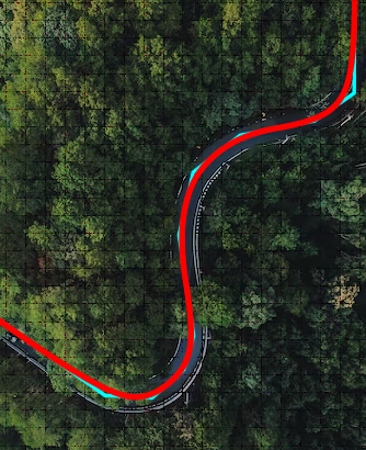
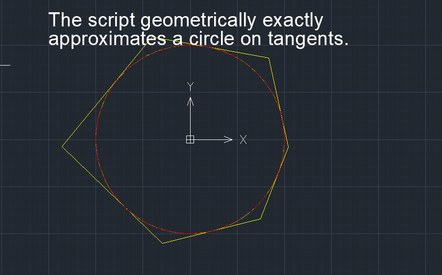
2) the road route must provide a comfortable, safe ride on the vehicle, therefore it is necessary to achieve maximum smoothness of the route under given restrictions. The unique functions of C3D FairCurveModeler for constructing curves on a tangent polyline allow you to design a road route defined by a polyline of theodolite traverses with high quality smoothness and minimizing the length of the route and its potential energy
3) the cam profile determines the movement of the pusher with the valve to ensure the necessary gas distribution law, therefore, when designing it, it is recommended to achieve shock-free smooth movement of the valve. The proposed modeling techniques in the application allow you to achieve 9th order smoothness! integral curve with exact arcs of circles of the upper and lower “stand”.
The transition section between the sections of the stand in the form of a NURBzS curve of the 8th degree. Provides 7th order of smoothness
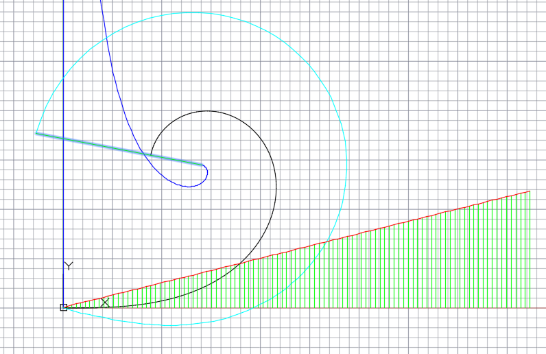
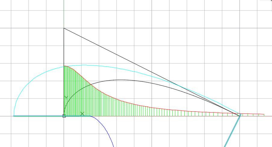
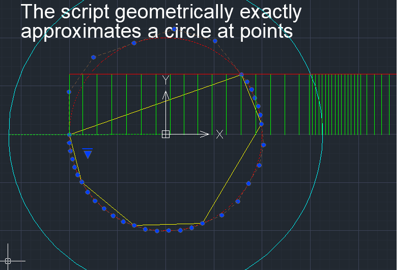
4) among the functional curves, a subclass of engineering analytical curves can be distinguished, which provide the design characteristics of the object in the only optimal way. Such curves, for example, include the Archimedes spiral, used to construct the profile of the teeth of a gear, as well as the brachistochrone, the steepest descent curve for transporting objects. A catenary line, used to model the surface of a dome or suspended structure, and a clothoid, used to design superelevation sections with a linear change in centrifugal force starting from zero, are also examples of engineering analysis curves. The proposed approximation techniques in the application make it possible to approximate analytical curves isogeometrically (while preserving the shape and basic properties).
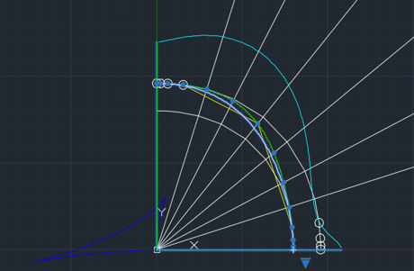
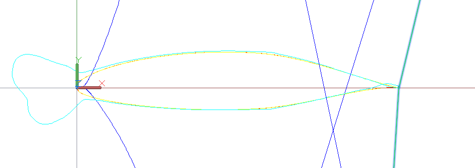
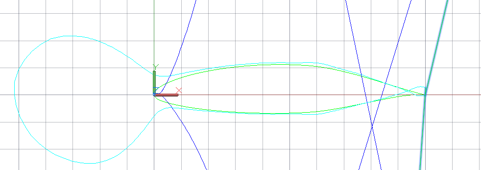
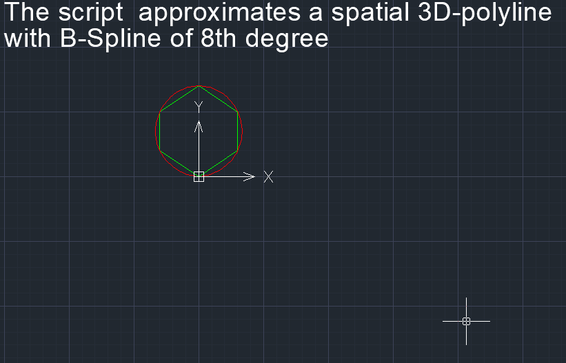
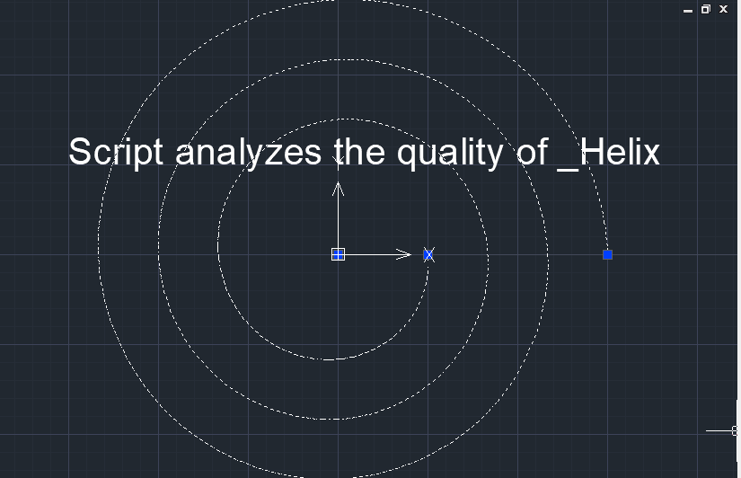
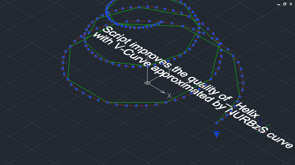
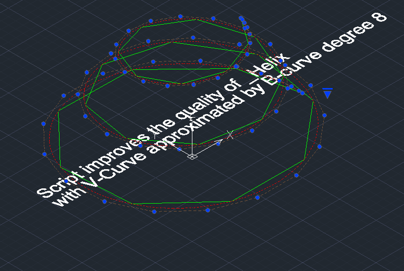
An 8th degree B-spline curve approximates the points of the _Helix AutoCAD primitive. Ideal curvature plot and evolute of a B-spline curve (shown in red). The evolute of the standard _Helix AutoCAD primitive is shown in blue color.
5) in industrial design/engineering problems, the construction of curves with monotonic curvature is often required. In addition to commands for approximating fixed analytical curves in the application allows you to use three additional commands for constructing aesthetic curves:
- the initial section of the clothoid with specifying the length and final curvature;
- Maclaurin Sectrix - a section of a curve with monotonic curvature, defined by an osculating triangle;
- site of a B-spline curve with monotonic curvature by generating the vertices of an open S-polygon with a given link elongation factor and a fixed angle between links.
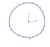
Section of a 4th degree B-spline curve with monotonic curvature (elongation factor 2, angle 90 degrees).
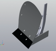
Replacing a parabola-shaped guide curve in the standard plow design with a clothoid section with the same macroparameters allowed us to obtain an amazing result: the quality of plowing increased and the energy intensity of processing decreased.
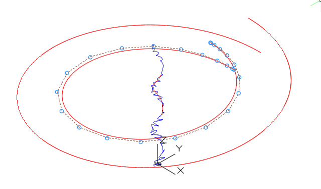
6) in reverse engineering, the problem of approximating a curve defined by an array of “noisy” points arises. Precise interpolation results in a curve with oscillation of curvature. The FairCurveModeler commands for constructing smoothing curves solve this problem.
Before and after smoothing.
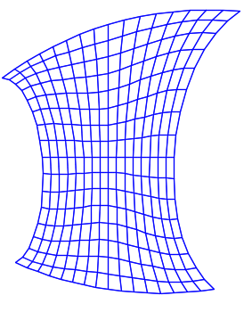
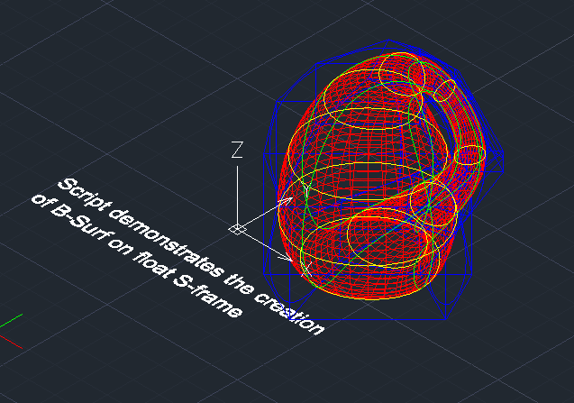
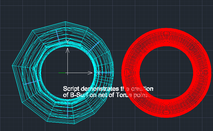
7) the application implements commands for constructing B-spline surfaces. A frame-kinematic method for representing a B-spline surface of arbitrary format has been developed. The construction of a frame-kinematic B-spline surface is divided into 2 stages:
The first stage is the construction of generating B-spline curves of class F.
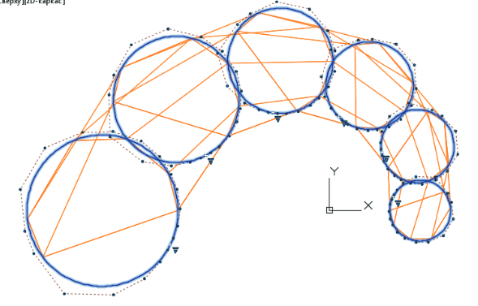
The second stage is the construction of directing B-spline curves of class F on the columns of the network of S-polygons of forming curves.

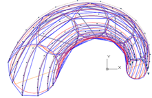
The S-polygon frame of the B-spline guide curves forms the S-frame of the B-spline surface.
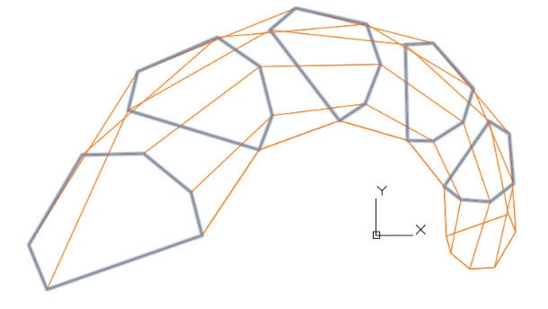
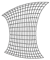
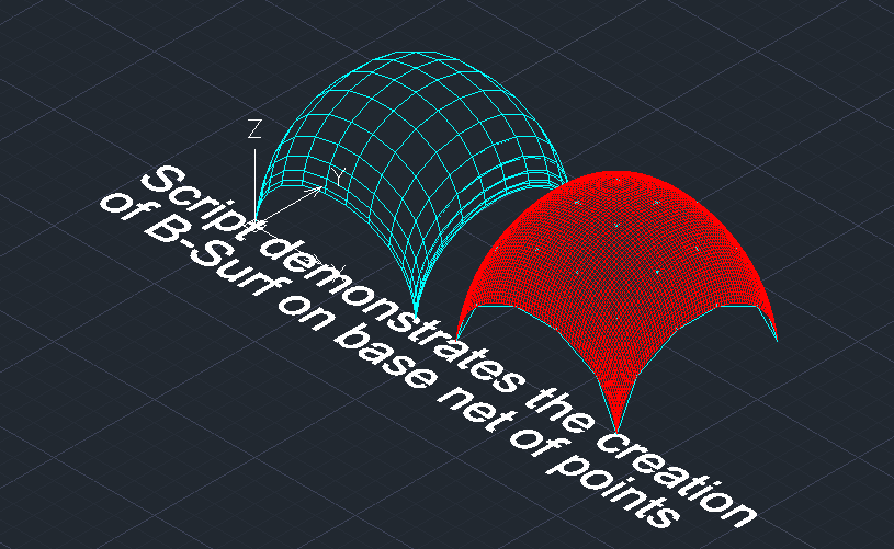
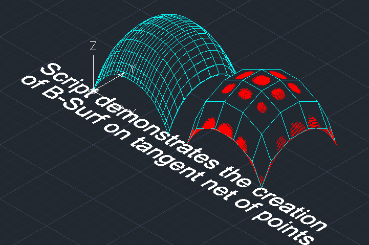
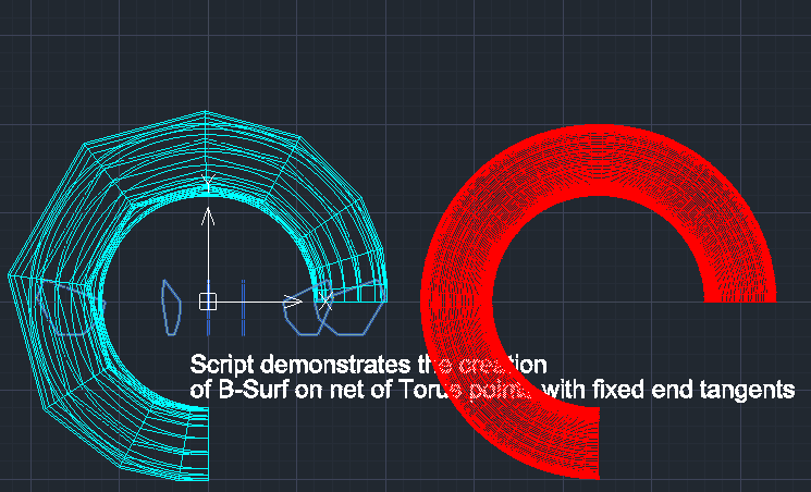
8) using the option of constructing generators and guides of surface along a tangent allows you to construct surfaces tangent to the original polyhedron from a network of points. This can be useful when freely designing industrial design products. In this case, it is as if an array of material is given and, in order to obtain a masterpiece, in the words of Michelangelo, “everything unnecessary is removed.”
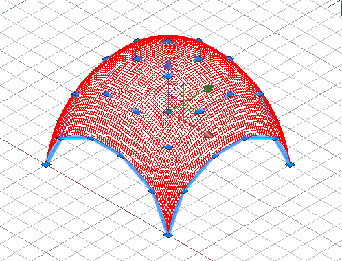
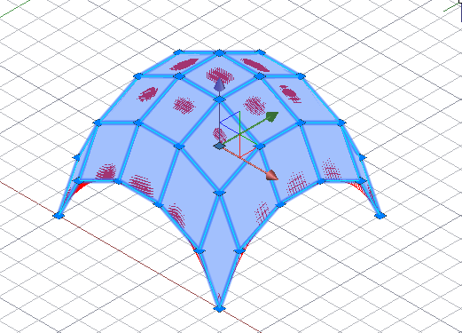
Construction of a surface on a reference network and on a tangent network.
9) the external body surface of a car, architectural curvilinear forms of a building, forms of industrial design products can be classified as functional surfaces, if aesthetics and beauty are considered as a design characteristic of a product, which determines its consumer properties. The absence of oscillation of isoparametric surface curves is extremely important. The presence of oscillating isoparametric curves leads to the effect of “curved mirrors”. The proposed modeling techniques in the application allow us to eliminate oscillating isoparametric curves on the projection.
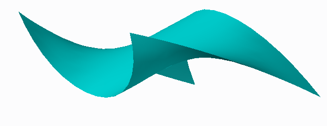
Before and after correction.
Using FairCurveModeler – is a simple, fast and cheap way to improve the quality of a product!
General Usage Instruction
Command V_Model this is the main command of the Application. The command creates smooth curves and surfaces. The command has a complex structure of bar menu-style options. The specific set of options depends on the selected object:
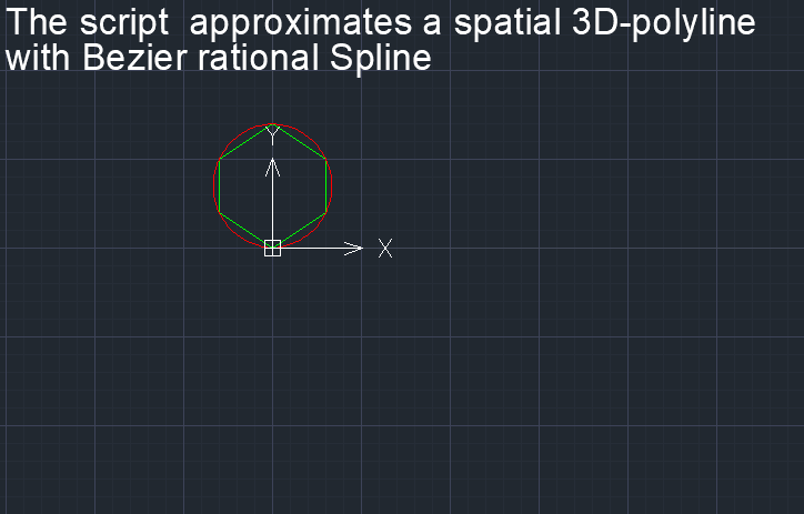
1) 3D polyline - used to edit and create a smooth V-curve and approximate the created V-curve through a rational Bezier spline (NURBzS) curve or B-curve. A 3D polyline can be used as a reference polyline or tangent polyline, and can be used directly as S-polygons for a B-spline curve. A set of 3D polylines can be combined into a polygon mesh 3D Mesh to construct a B-surface.
2) Hermite GD (Hermite Geometrical Determinant) - is represented as a '3D polyline' primitive. A 3D polyline passes base points, tangent vectors, curvature vectors in the following sequence: base point > end of tangent vector > return to base point > end of curvature vector > return to base point > move to next base point > ... Thus, a 3D polyline completely provides information about the parameters of the Hermite GD of the 2nd order of fixation. You can edit the Hermite GD using standard CAD tools, preserving the GD structure. You can directly construct a NURBzS curve on the Hermite GD of the 2nd order of fixation. You can directly construct a B-curve on the Hermite GD of the 1st order of fixation. On the base polyline of the Hermite GD or on the tangent lines of the Hermite GD, you can construct V-curves with approximation using NURBzS-curves or B-curves. GD parameters at end points and inflection points can be used when constructing a V-curve. Methods for constructing a V-curve also make it possible to fix the given directions of the Hermite GD tangents. Detailed .
3) NURBzS curve (created on a 3D polyline or on Ermita GD) - this is the standard form of spline representation in Autodesk® AutoCAD®.
4) NURBS curve (created directly by on a 3D polyline or by Hermite) - this is the standard form of spline representation in AutoCAD . NURBS curve can be edited using S-polygon with quality testing using curvature and evolute graphs.
5) 3D Mesh - the polygonal network is used: - to create generating smooth V-curves on rows and approximation using B-spline curves, then to construct B-spline guide curves on the columns of 3D Mesh of S-polygons of generating B-spline curves. And on the frame of B-spline guide curves, create a B-spline surface (NURBS surface).
6) The B-curveframework is used to construct B-spline guides. It is represented by a polygonal network composed of S-polygons of B-curves. B-spline guide curves are cdeated on the columns of network of the 3D S-polygons to create a B-spline surface (NURBS surface).
7) The NURBS surfaceis created on the frame of guide B-curves in the Application. You can check the quality of the surface, create parallel surfaces. To convert NURBS Application surfaces to AutoCAD primitives, you must convert Application surfaces geometrically accurately via IGS format to NURBS AutoCAD surfaces. You can edit a B-spline surface using an s-frame with quality testing and editing the shape of an arbitrary isoparametric curve.
8) Two additional commands (V_Aesthetic, V_Hermite)are designed for modeling aesthetic and engineering curves based on analytical curves. When designing industrial design products and products with functional curves, curves with certain properties are often required: aesthetic curves with a monotonous change in curvature (clothoid and Maclaurin Sectrix), a chain line for modeling domes or hanging structures; line of steepest descent to synchronize the time of movement of particles under the influence of gravity from any point on the curve to the end point; the same clothoid with a linear change in curvature for tracing the road; etc. The Application allows the use of various analytical curves. Example.
The application does not allow you to test or edit spline polylines directly. Pre-convert spline polylines to real NURBS curves: Command:_Spline > Object > Select spline polylines.
Testing and training using scripts
Команды
| Значок | Команда | Описание команды |
|---|---|---|

|
Constructs high quality curves and surfaces based on smoothness criteria. |
|

|
Constructs sections of the clothoid, the Maclaurin sector, the “typical curve”. |
|

|
Constructs NURBS curves based on analytical curves specified by a table of coordinates of points, tangent vectors and curvature values. Pre-prepare a table of analytical curve parameters in MathCAD Laboratory work. Preparation of NURBS templates of analytical curves for CAD systems |
Rules / Restrictions
FairCurveModeler is a specialized CAD application developed for geometric modeling of functional curves. The quality of functional curves directly determines the quality of designed products in aircraft manufacturing, shipbuilding, automotive manufacturing, engine manufacturing and many other industries.
There are invariant, relative to the specifics of industries, requirements for the quality of functional curves: - high order of smoothness; - the minimum number of curvature extrema; - smoothness of the curvature graph / limitation on the rate of change of curvature; - smooth torsion; - restrictions on the maximum value of curvature; - smoothness of torsion of the spatial curve; - low potential energy.
Geometric modeling of functional curves is performed at the stage of preliminary design of the product. At the preliminary design stage, a theoretical drawing / theoretical geometric model of the product is determined. Accordingly, a theoretical drawing of a curve or a theoretical model of a curve.
The cost of error or poor construction of function curves can be very large and cost a lot of money in these industries. And this is fraught not only with loss of money, but also with loss of competitiveness. The proposed rules and restrictions when constructing curve models make it possible to guarantee high quality of modeled curves and, accordingly, high quality of the product.
The curve model is created on the basis of a discrete curve model, the so-called, geometric determinant (GD). The FairCurveModeler application uses three types of GD: a base polyline, a tangent polyline to determine a flat curve, and a Hermite GD.The Hermite GO is a base polyline equipped at all vertices with tangent vectors [and curvature vectors]. To determine spatial curves, instead of a tangent polyline, the Hermite GD is used, equipped at the vertices of the polyline with only tangent vectors. This is a Hermite GD of the first order of fixation. In the general case, the points and tangent vectors of a spatial polyline define non intersecting straight lines.
The base polyline can be equipped with tangent vectors and curvature vectors at the end vertices and with fixed tangent vectors at some vertices. A tangent polyline or Hermite GD of the first order of fixation can be equipped with curvature vectors at the end vertices and fixed points on the tangent lines. In addition to geometric parameters of the type of base polyline, tangent vectors and curvature vectors, the GD may contain additional parameters of the type of conditions and constraints (a certain order of smoothness, permissible maximum values of curvature and rate of change of curvature).
The complete geometric curve model (Curve Determinator) contains GD + isogeometric approximation methods using NURBS curves. In the FairCurveModeler system, these are methods for isogemetric construction of a B-spline curve and a rational Bezier spline curve (NURBzS curve).
During the geometric modeling of curves, metrological requirements must be met. First of all, metrological determinity must be ensured. All the required properties of the functional curve must be specified in the structure of GD and the approximating curve must have exactly these properties.
In the FairCurveModeler system, metrological determinity is ensured by strict isomorphism (isogeometricity) of the curve structure and the GD structure. The shape of the curve and its parameters are uniquely determined by the shape and parameters of the GO. That is, GO 1) positions the curve on the GD with the exact passage of the curve through the vertices of the base polyline / touching the links of a flat tangent polyline / touching the tangent lines of the spatial GD; 2) determines the shape up to the number of inflection points (the number of locally convex sections); 3) determines areas of monotonic change in curvature on the curve.
A curve determinant with GD brought to metrological standards ensures high quality of the curve according to the criteria given above. To bring GD to the standard of metrological determinity, unique methods of the FairCurveModeler system are used: smoothing, reparameterization and harmonization.
To ensure metrological determinity, certain rules for designing a base/tangent polyline have been adopted. In the “ab-initio” or “tabula rasa” paradigm, the designer can begin to prepare a geometric structure according to the rules for constructing a regular polyline. A regular polyline is formed according to the following rules. The angles between the links are > 90, the straight sections of the curve are specified by the vertices on the straight line. The expressiveness of the form is ensured by the restriction on the minimum deflection of the insole, the restriction on the difference in the lengths of adjacent links. Equipping the GD with additional parameters such as fixed tangents on the base polyline or fixed points on the tangent polyline should not contradict the shape of the control polyline. Fixed points must have adjacent points free from fixation.
These rules and restrictions make it possible to unambiguously define the shape of the curve. That is, they provide metrological determinity for specifying the shape of the curve.
However, to define a curve with sections of monotonous changes in curvature, you need to be able to form polyines of a harmonious shape. The harmonious shape of a polyline is a shape of a polyline in which the vertices of the polyline are distributed along the contour of the polyline with a density proportional to the curvature. In this case, the graph of the discrete approximation of the curvature along the length of the polyline uniquely determines the graph of the curvature of the approximating curve.
In the FairCurveModeler system, to build a harmonious shape of polyline, the designer can use various techniques in the system: - form the so-called typical polylines (command genFrame ) - take points from analytical curves with monotonic curvature ( Clothoid or Sectrix ). - execute the command to harmonize the original regular polyline ( gaRmonize ). A harmonized polyline single-handedly determines sections of a curve with a monotonic change in curvature.
The designer does not always work in the “ab-initio” paradigm. To sketch the curve, measured data from a scanner or data from paper drawing tables, which are noisy data, may be provided. The sequence of bringing these data to a theoretical drawing with metrological determinity is as follows: 1) The onMiddleLine smoothing command along the middle line is executed. First, a rough base polyline is drawn on the measured data. Then a polyline of noisy points is indicated. The smoothing command algorithm constructs a curve on the base polyline and then deforms this curve in such a way that the sum of deviations of noisy points “to the left” of the curve is equal to the sum of deviations “to the right”. That is, the resulting curve is the average line relative to the noisy points. 2) The resulting smoothed curve is reparameterized by Transform > Reparam. In this case, the nodes of the reparameterized curve are harmoniously redistributed along the contour of the curve. 3) GD is extracted from the reparameterized curve Transform > toHermite. 4) GD is smoothed in a given corridor OnCoridor . At the same time, the quality of the curve improves. When smoothing with this option, the smoothness of the curve improves.
GD + variants of approximating curves brought to the standard of metrological determinity is the metrologically determined Curve Determinant. At the same time, the GD curve contains all the parameters for monitoring the quality of the curve at all stages of design, testing and manufactoring of the product.
Installation/Removal
Unzip to C:/ with the option "to current folder" FairCurveModeler.zip Two folders should appear: c:/FairCurveModeler c:/FairCurveModeler_TEMP Run c:/FairCurveModeler/Exec/WebFairCurveExe.exe as administrator. Confirm your registration in the registry. Launch ZWCAD / BricsCAD / AutoCAD. Load ZWCAD / BricsCAD / AutoCAD applications from the folder c:/FairCurveModeler/Lisp/ LISP_C3DFCModeler_Com.lsp s_init_zwcad.lsp Create a new drawing. Use the scripts in the Scripts folder to 1) checking the functionality of the application; 2) for training. Calling help information in the CAD system: V_Help_Ru Calling references from folders c:/FairCurveModeler/Help_RU/Help_Ru.html Start executing commands yourself.
Deleting an application Run as administrator c:/FairCurveModeler/Exec/v_unreg.bat Delete folders c:/FairCurveModeler c:/FairCurveModeler_TEMP